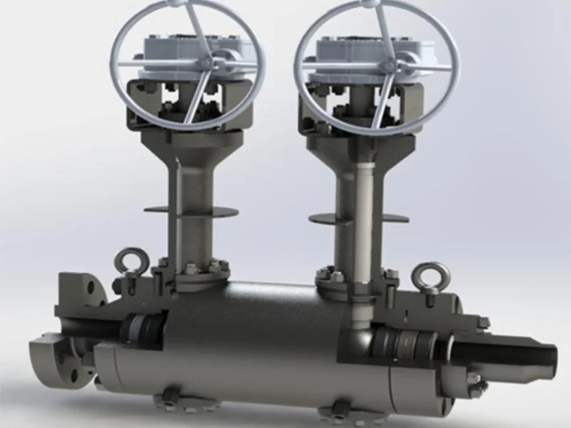
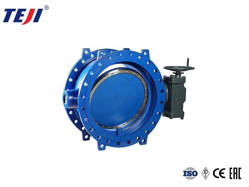
يعتمد معدل تدفق وسرعة الصمام بشكل أساسي على قطر الصمام، ويرتبط أيضًا بمقاومة هيكل الصمام للوسط، ويرتبط بشكل جوهري بعوامل مثل ضغط الصمام ودرجة الحرارة وتركيز الوسط.
ما هي العلاقة بين الاثنين بالضبط؟
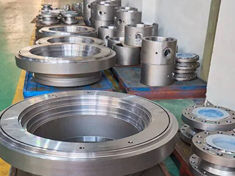
The flow channel area of a valve is directly related to flow velocity and flow rate, and flow velocity and flow rate are two mutually dependent quantities. When the flow rate is constant, the flow velocity is larger, and the channel area can be smaller; If the flow velocity is low, the runner area can be larger. Conversely, a large flow channel area has a lower flow velocity; The smaller the flow channel area, the higher the flow velocity.
If the medium has a high flow velocity, the valve diameter can be smaller, but resistance loss is greater and the valve is prone to damage. High flow velocity can cause static electricity effects on flammable and explosive media, posing dangers; If the flow rate is too low, efficiency is low and uneconomical. For media with high viscosity and explosive value, a lower flow rate should be used. For oils and liquids with high viscosity, the flow rate should be adjusted according to viscosity, generally 0.1~2m/s.
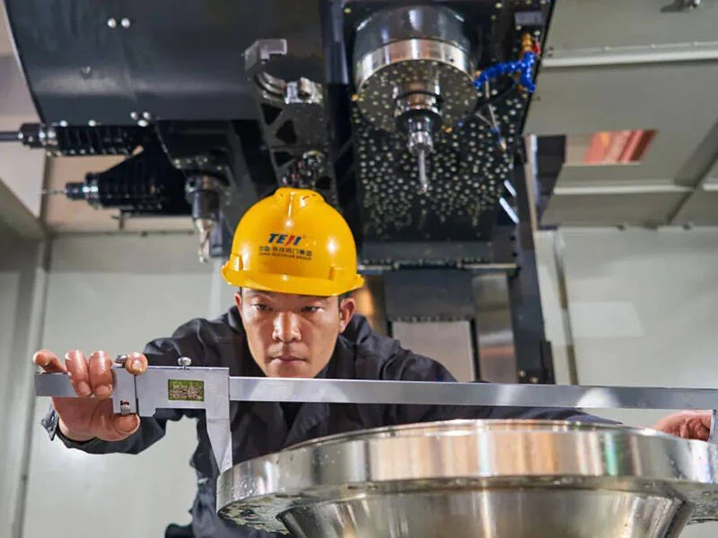
Generally, the flow rate is known, and the flow rate can be determined by experience. The nominal diameter of the valve can be calculated by analyzing flow rate and flow rate.
Valves with the same diameter may have different structural types, resulting in different fluid resistance. Under the same conditions, the greater the valve’s resistance coefficient, the more the flow rate and flow rate of the fluid through the valve decrease; The lower the valve resistance coefficient, the less the flow rate and flow rate of fluid passing through the valve decrease.
Overview of Common Flow Rates for Various Media
| اسم السائل |
شروط الاستخدام |
Flow rate
(m/s) |
| البخار المشبع |
DN>200
DN=200~100
DN<100 |
30~40
25~35
15~30 |
| البخار المحموم |
DN>200
DN=200~100
DN<100 |
40~60
30~50
20~40 |
| بخار منخفض الضغط |
ع <1.0 (الضغط المطلق) |
15 ~ 20 |
| بخار متوسط الضغط |
P=1.0~4.0(الضغط المطلق) |
20~40 |
| بخار عالي الضغط |
P=4.0~12.0(الضغط المطلق) |
40~60 |
| الغاز المضغوط |
Vacuum
P≤0.3(Gauge pressure)
P=0.3~0.6(Gauge pressure)
P=0.6~1.0(Gauge pressure)
P=1.0~2.0(Gauge pressure)
P=2.0~3.0(Gauge pressure)
P=3.0~30.0(Gauge pressure) |
5~10
8~12
10~20
10~15
8~12
3~6
0.5~3 |
| الأكسجين |
P=0~0.05(Gauge pressure)
P=0.05~0.6(Gauge pressure)
P=0.6~1.0(Gauge pressure)
P=1.0~2.0(Gauge pressure)
P=2.0~3.0(Gauge pressure) |
5~10
7~8
4~6
4~5
3~4 |
| غاز الفحم |
|
2.5 ~ 15 |
| غاز شبه ماء |
P = 0.1–0.15 (مقياس) |
10 ~ 15 |
| الغاز الطبيعي |
|
30 |
| نتروجين |
ف = 5-10 (مطلق) |
15 ~ 25 |
| الأمونيا |
Vacuum
P < 0.3 (gauge)
P < 0.6 (gauge)
P ≤ 2 (gauge) |
15~25
8~15
10~20
3~8 |
| ماء الأسيتيلين |
|
30
5~6 |
| غاز الأسيتيلين |
p < 0.01 (gauge)
p < 0.15 (gauge)
p < 2.5 (gauge) |
3~4
4~8
5 |
| أبخرة |
Gas
Liquid |
10~25
1.6 |
| كبريتيد الهيدروجين |
Gas
Liquid |
20
1.5 |
| الكريبتون السائل |
Vacuum
P ≤ 0.6 (gauge)
P ≤ 2.0 (gauge) |
0.05~0.3
0.3~0.8
0.8~1.5 |
| أرجوكسيد الصوديوم |
Concentration 0–30%
Concentration 30%–50%
Concentration 50%–73% |
2
1.5
1.2 |
| حمض الكبريتيك |
Concentration 88%–93%
Concentration 93%–100% |
1.2
1.2 |
| حمض الهيدروكلوريك |
|
1.5 |
| Water and viscosity
Similar liquids |
P = 0.1–0.3 (gauge pressure)
P ≤ 1.0 (gauge pressure)
P ≤ 8.0 (gauge pressure)
P ≤ 20–30 (gauge pressure)
Heating network circulating water, cooling water
Pressure return water
Non-pressurized return water |
0.5~2
0.5~3
2~3
2~3.5
0.3~1
0.5~2
0.5~1.2 |
| ماء الصنبور |
Main pipe P = 0.3 (gauge pressure)
Branch pipe P = 0.3 (gauge pressure) |
1.5~3.5
1~1.5 |
| مياه تغذية الغلايات |
|
>3 |
| مكثفات البخار |
|
0.5 ~ 1.5 |
| المكثفات |
تدفق الجاذبية |
0.2~0.5 |
| الماء المسخن |
|
2 |
| مياه البحر، مياه قلوية قليلاً |
P <0.6 (قياس الضغط) |
1.5 ~ 2.5 |
Note:
The unit for DN value is: mm; The unit of Rho value is: MPa.
Gate valves have a low resistance coefficient, only within the range of 0.1~1.5; large-diameter gate valves have a resistance coefficient of 0.2~0.5; shrink-mouth gate valves have a higher resistance coefficient.
The resistance coefficient of globe valves is much higher than that of gate valves, generally between 4~7. Y-type globe valves (DC type) have the lowest resistance coefficient, between 1.5~2.
Forged steel globe valves have the highest resistance coefficient, sometimes reaching as high as 8.
The resistance coefficient of check valves depends on their structure: swing check valves are usually about 0.8~2, with multi-disc swing check valves having a higher resistance coefficient; lifting type check valves have the highest resistance coefficient, up to 12. The plug valve has a low resistance coefficient, usually about 0.4~1.2.
The resistance coefficient of diaphragm valves is generally around 2.3. The resistance coefficient of butterfly valves is low, generally within 0.5. The resistance coefficient of ball valves is the lowest, generally around 0.1.
The resistance coefficient of the above valve is the value when the valve is fully open.
يجب أن يأخذ اختيار قطر الصمام في الاعتبار دقة تصنيع الصمام، وانحرافات الأبعاد، وعوامل أخرى. يجب أن يكون لقطر الصمام هامش معين، بشكل عام 15%. في التشغيل الفعلي، يتم تحديد قطر الصمام بواسطة قطر خط أنابيب العملية.