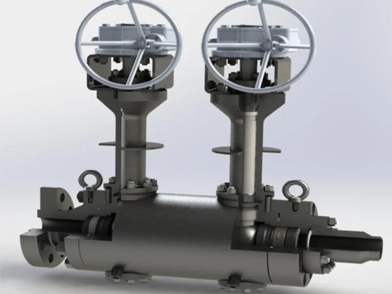
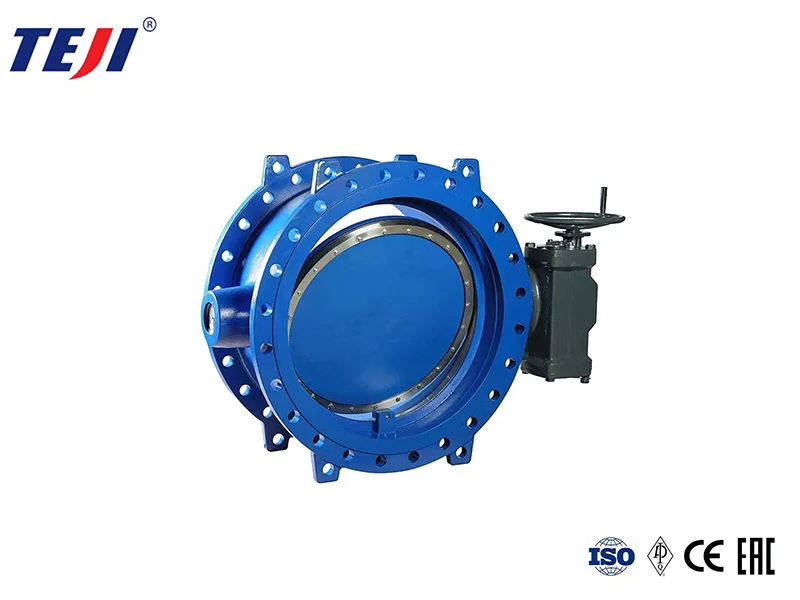
El caudal y la velocidad de una válvula dependen principalmente del diámetro de la válvula, también están relacionados con la resistencia de la estructura de la válvula al medio y están intrínsecamente relacionados con factores como la presión de la válvula, la temperatura y la concentración del medio.
¿Cuál es exactamente la relación entre los dos?
The flow channel area of a valve is directly related to flow velocity and flow rate, and flow velocity and flow rate are two mutually dependent quantities. When the flow rate is constant, the flow velocity is larger, and the channel area can be smaller; If the flow velocity is low, the runner area can be larger. Conversely, a large flow channel area has a lower flow velocity; The smaller the flow channel area, the higher the flow velocity.
If the medium has a high flow velocity, the valve diameter can be smaller, but resistance loss is greater and the valve is prone to damage. High flow velocity can cause static electricity effects on flammable and explosive media, posing dangers; If the flow rate is too low, efficiency is low and uneconomical. For media with high viscosity and explosive value, a lower flow rate should be used. For oils and liquids with high viscosity, the flow rate should be adjusted according to viscosity, generally 0.1~2m/s.
Generally, the flow rate is known, and the flow rate can be determined by experience. The nominal diameter of the valve can be calculated by analyzing flow rate and flow rate.
Valves with the same diameter may have different structural types, resulting in different fluid resistance. Under the same conditions, the greater the valve’s resistance coefficient, the more the flow rate and flow rate of the fluid through the valve decrease; The lower the valve resistance coefficient, the less the flow rate and flow rate of fluid passing through the valve decrease.
Overview of Common Flow Rates for Various Media
| Nombre del fluido |
Condiciones de uso |
Flow rate
(m/s) |
| Vapor saturado |
DN>200
DN=200~100
DN<100 |
30~40
25~35
15~30 |
| Vapor sobrecalentado |
DN>200
DN=200~100
DN<100 |
40~60
30~50
20~40 |
| Vapor de baja presión |
p<1,0 (presión absoluta) |
15~20 |
| Vapor de media presión |
P=1,0~4,0(Presión absoluta) |
20~40 |
| Vapor de alta presión |
P=4,0~12,0(Presión absoluta) |
40~60 |
| Gas comprimido |
Vacuum
P≤0.3(Gauge pressure)
P=0.3~0.6(Gauge pressure)
P=0.6~1.0(Gauge pressure)
P=1.0~2.0(Gauge pressure)
P=2.0~3.0(Gauge pressure)
P=3.0~30.0(Gauge pressure) |
5~10
8~12
10~20
10~15
8~12
3~6
0.5~3 |
| Oxígeno |
P=0~0.05(Gauge pressure)
P=0.05~0.6(Gauge pressure)
P=0.6~1.0(Gauge pressure)
P=1.0~2.0(Gauge pressure)
P=2.0~3.0(Gauge pressure) |
5~10
7~8
4~6
4~5
3~4 |
| gas de hulla |
|
2,5~15 |
| gas semi-agua |
P = 0,1–0,15 (medidor) |
10~15 |
| Gas natural |
|
30 |
| Nitrógeno |
P = 5–10 (absoluto) |
15~25 |
| Amoníaco |
Vacuum
P < 0.3 (gauge)
P < 0.6 (gauge)
P ≤ 2 (gauge) |
15~25
8~15
10~20
3~8 |
| agua con acetileno |
|
30
5~6 |
| gas acetileno |
p < 0.01 (gauge)
p < 0.15 (gauge)
p < 2.5 (gauge) |
3~4
4~8
5 |
| Humos |
Gas
Liquid |
10~25
1.6 |
| sulfuro de hidrógeno |
Gas
Liquid |
20
1.5 |
| criptón líquido |
Vacuum
P ≤ 0.6 (gauge)
P ≤ 2.0 (gauge) |
0.05~0.3
0.3~0.8
0.8~1.5 |
| argóxido de sodio |
Concentration 0–30%
Concentration 30%–50%
Concentration 50%–73% |
2
1.5
1.2 |
| Ácido sulfúrico |
Concentration 88%–93%
Concentration 93%–100% |
1.2
1.2 |
| Ácido clorhídrico |
|
1.5 |
| Water and viscosity
Similar liquids |
P = 0.1–0.3 (gauge pressure)
P ≤ 1.0 (gauge pressure)
P ≤ 8.0 (gauge pressure)
P ≤ 20–30 (gauge pressure)
Heating network circulating water, cooling water
Pressure return water
Non-pressurized return water |
0.5~2
0.5~3
2~3
2~3.5
0.3~1
0.5~2
0.5~1.2 |
| agua del grifo |
Main pipe P = 0.3 (gauge pressure)
Branch pipe P = 0.3 (gauge pressure) |
1.5~3.5
1~1.5 |
| Agua de alimentación de calderas |
|
>3 |
| Condensado de vapor |
|
0,5~1,5 |
| Condensar |
flujo de gravedad |
0,2 ~ 0,5 |
| agua sobrecalentada |
|
2 |
| Agua de mar, agua ligeramente alcalina. |
P < 0,6 (presión manométrica) |
1,5~2,5 |
Note:
The unit for DN value is: mm; The unit of Rho value is: MPa.
Gate valves have a low resistance coefficient, only within the range of 0.1~1.5; large-diameter gate valves have a resistance coefficient of 0.2~0.5; shrink-mouth gate valves have a higher resistance coefficient.
The resistance coefficient of globe valves is much higher than that of gate valves, generally between 4~7. Y-type globe valves (DC type) have the lowest resistance coefficient, between 1.5~2.
Forged steel globe valves have the highest resistance coefficient, sometimes reaching as high as 8.
The resistance coefficient of check valves depends on their structure: swing check valves are usually about 0.8~2, with multi-disc swing check valves having a higher resistance coefficient; lifting type check valves have the highest resistance coefficient, up to 12. The plug valve has a low resistance coefficient, usually about 0.4~1.2.
The resistance coefficient of diaphragm valves is generally around 2.3. The resistance coefficient of butterfly valves is low, generally within 0.5. The resistance coefficient of ball valves is the lowest, generally around 0.1.
The resistance coefficient of the above valve is the value when the valve is fully open.
La selección del diámetro de la válvula debe tener en cuenta la precisión del mecanizado de la válvula, las desviaciones dimensionales y otros factores. El diámetro de la válvula debe tener un cierto margen, generalmente del 15%. En funcionamiento real, el diámetro de la válvula está determinado por el diámetro de la tubería de proceso.